

What Your Solar Site Plan Reveals That Other Documents Cannot
Solar plan sets contain several critical documents, but among all of them, the site plan carries a unique burden. It is the one document that places the entire installation in physical context — showing reviewers exactly where the system sits on the property, how it relates to surrounding structures, where the utility connection points are, and whether the layout respects every safety and access requirement the local jurisdiction enforces. A technically perfect electrical diagram means nothing if the site plan beneath it is inaccurate or incomplete. PTOEdge has reviewed thousands of solar submissions across the country, and site plan errors rank consistently among the top reasons otherwise solid applications get returned for correction.
Understanding what a site plan must communicate — and why that communication has to be precise — is essential knowledge for anyone involved in moving a solar project from design to permitted installation. Solar plan sets live or die by the accuracy of their foundational documents, and the site plan is where that foundation is laid.
If your site plan has gaps you have not caught yet, your permit submission is already at risk — have a documentation specialist review your package before it costs you weeks.
What a Solar Site Plan Is Actually Showing
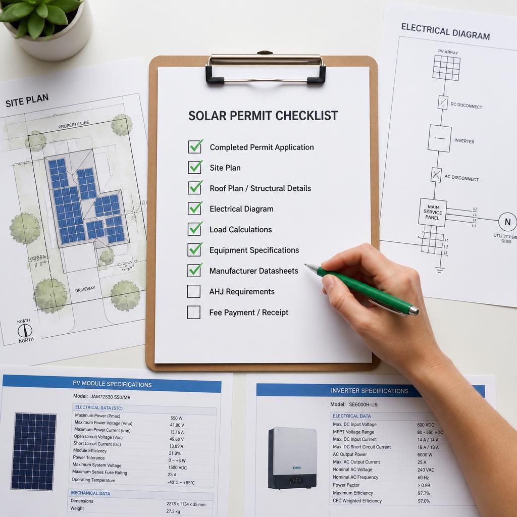
A site plan is a scaled overhead view of the entire property on which the solar installation will occur. At minimum, it communicates several layers of information that no other document in the plan set replicates:
- The property boundary and its relationship to the structure being served
- The location of the solar array relative to the roof or ground mount area
- The path of electrical conduit from the array to the main service panel and utility meter
- The location of the main electrical panel, disconnect, and point of interconnection
- Setback distances from roof edges, ridgelines, hips, valleys, and obstructions such as skylights or HVAC equipment
- North arrow and scale bar, which allow reviewers to independently verify dimensions
Each of these elements serves a distinct purpose for a different reviewer. The building department uses the property layout and setback data. The fire department uses the access pathway and setback information to confirm emergency responder access. The utility company references the conduit path and interconnection point location. Miss any one of these, and you have handed a different reviewer a reason to flag your application.
Why Site Plan Accuracy Drives the Whole Review Cycle
The site plan is reviewed before most other sections of a solar plan set. It orients the reviewer to the project before they look at any technical details. If the site plan is confusing, inconsistent with the roof plan, or missing required elements, reviewers often flag the application at this early stage without proceeding further — meaning your entire submission is sent back before anyone even reached your electrical diagram.
This sequential review structure means that site plan quality has an outsized effect on overall permit timeline. A clean, complete, scaled site plan that matches the roof plan, reflects actual field conditions, and includes all jurisdiction-required notations moves reviewers quickly and confidently through the rest of the package. A site plan that raises questions — even minor ones — invites scrutiny that slows the entire process.
Furthermore, when building departments and fire departments review the same submission simultaneously, a site plan error that flags one department automatically affects the other department's timeline too. Both must sign off before a permit issues, so a flag from either one resets the entire review clock.
The Setback Rules That Catch Installers Off Guard
Fire access setbacks are one of the most jurisdiction-specific and frequently misunderstood requirements in solar site planning. The general principle is consistent — fire departments need clear pathways on rooftops to perform ventilation operations during a structure fire — but the specific measurements vary considerably between jurisdictions.
California has adopted detailed fire setback standards through its state fire code, but local jurisdictions often layer additional requirements on top. Some require a minimum three-foot clear path on all roof edges. Others require clear access to the ridge. A few require specific unobstructed areas near skylights and roof hatches.
In other states, setback requirements may be governed entirely by local fire codes with no statewide standard at all. What is acceptable in one county may be rejected two counties over. Using a site plan template that was prepared for a different jurisdiction — without verifying the setback standards of the current AHJ — is one of the most common and most preventable sources of permit rejection.
This is precisely where Permit Design & AHJ Compliance expertise becomes a genuine project asset. Knowing the specific setback requirements for each jurisdiction, and drafting the site plan to reflect those requirements from the start, eliminates one of the most frequent sources of review delays.
Scale and Measurement: The Technical Details That Matter More Than People Expect
A site plan that is not drawn to scale is not technically a site plan in the eyes of most building departments — it is a sketch. Reviewers use the scale bar and stated drawing scale to independently verify that setback distances, panel array dimensions, and clearance measurements match what is shown graphically. If the numbers do not match the drawing, the application is returned.
Common scale-related errors in solar plan sets include:
- Stating a scale (such as 1 inch = 20 feet) that does not actually match the drawn dimensions
- Omitting the scale bar entirely, forcing reviewers to reject on a technicality even when the content is otherwise accurate
- Mixing measurement systems within the same plan set, using feet in one section and meters in another without conversion notation
- Drawing panel arrays at the wrong size relative to the roof, which makes setback measurements appear compliant when they are not
These errors are not always obvious at a glance. They often require a careful comparison between the graphic representation and the stated dimensions — exactly the kind of cross-check that a thorough internal review catches before submission.
Conduit Path and Interconnection Notation: What Utilities Need to See
While building departments focus primarily on the structural and fire-safety elements of a site plan, utility companies reviewing interconnection applications look closely at how the conduit path is depicted and where the point of interconnection is located. This information tells utility engineers what to expect when they conduct their own field verification, and inconsistencies between the site plan and the actual installation create problems during that verification.
The site plan should clearly show:
- The conduit routing from the array to the inverter and from the inverter to the main panel
- The location of the AC and DC disconnects with approximate distances from the array and the service panel
- The utility meter location and its relationship to the main panel and point of interconnection
- Any metering upgrades or second meters required for net metering arrangements
When the PTO application reaches the utility company, their engineers compare the submitted interconnection documentation against the permitted plan set. A site plan that clearly and accurately shows all of these elements makes that comparison straightforward and accelerates the path toward permission to operate. When the site plan is vague or inconsistent, that comparison raises questions that slow the final approval stage.
Ground-Mount Projects: When Site Plans Carry Even More Weight
For ground-mounted solar installations, the site plan takes on additional complexity and importance. Unlike rooftop systems, ground mounts must address property line setbacks, grading and drainage considerations, access road requirements, and in some jurisdictions, visual screening mandates. All of these must be reflected in the site plan with sufficient detail to satisfy both building and zoning reviewers.
Zoning reviews for ground-mount systems frequently involve planning departments in addition to building departments, and planning reviewers look for information that building reviewers do not typically require. Lot coverage calculations, landscape buffer depictions, and proximity to property boundaries and easements are among the elements that must be present for a ground-mount site plan to pass a complete zoning review.
Preparing a ground-mount site plan without zoning review requirements in mind — even when the electrical and structural documentation is excellent — can produce a submission that clears the building department and fails at the planning department, extending the overall project timeline significantly.
Rooftop Systems: The Roof Plan Relationship That Cannot Be Overlooked
For rooftop installations, the site plan and the roof plan work together as a pair. The site plan shows the property-level context. The roof plan shows the array-level detail. These two documents must be consistent with each other in every dimension they share — roof footprint, panel placement, and setback distances must match exactly between the two drawings.
When reviewers find inconsistencies between the site plan and the roof plan within the same solar plan set, it signals that the documents were prepared independently without cross-referencing. That signal is not reassuring. It prompts a more careful review of everything else in the package, which takes more time and increases the chance of additional flags.
Why Every Detail in This Document Deserves Careful Attention
How Site Plan Quality Shapes Solar Installer Growth Over Time
Solar contractors who build strong site plan preparation habits early in their operations develop a structural advantage over time. Consistent first-submission approvals compound across every project in a pipeline — each one completing faster, requiring less administrative attention, and generating fewer customer service calls about permit status. Over a full project year, that difference in throughput is substantial and measurable.
Additionally, building departments remember contractors who submit consistently high-quality documentation. That reputation creates goodwill that can smooth future interactions in ways that are difficult to quantify but genuinely impactful.
Why Accurate Solar Plan Sets Begin With Getting the Site Plan Right
The site plan is where every solar project introduces itself to the people who must approve it. A solar stamping service that applies licensed engineering certification to site plan dimensions and structural attachment details adds a level of credibility that accelerates review in jurisdictions where stamped documents carry special authority. When the site plan is accurate, scaled, complete, and jurisdiction-specific, it sets a tone of professional competence that carries through the entire review process and supports a faster, cleaner path to project completion.
Your site plan is the first thing reviewers judge — make sure it reflects the quality your project deserves. Connect with a solar documentation expert and submit with confidence.
Frequently Asked Questions
What is the purpose of a site plan in a solar plan set?
A site plan provides an overhead, scaled view of the property showing the array location, conduit path, panel placement, setbacks, and interconnection point for review by building, fire, and utility authorities.
Why do solar site plans get rejected even when other documents are correct? Reviewers check the site plan first, and a single missing element — such as a scale bar, north arrow, or setback measurement — can trigger a rejection before the rest of the package is evaluated.
How do fire setback requirements vary between jurisdictions for solar installations? Fire setback standards differ significantly by city and county, with some requiring specific ridge access paths and others mandating clearance around roof obstructions, making jurisdiction research essential before drafting.
Do ground-mount solar installations require a different type of site plan?
Yes — ground-mount site plans must address property line setbacks, zoning requirements, drainage, and lot coverage in addition to the standard electrical and structural details required for rooftop systems.
How does an accurate site plan affect the utility interconnection approval?
Utility engineers compare the interconnection application against the permitted site plan, so a clear and accurate conduit path and interconnection point depiction directly speeds up the final permission to operate approval.
Catégories
Lire la suite
Difficult situations in life can affect emotional well-being, relationships, and confidence. Many people seek astrological guidance to find peace and practical solutions during such challenging times. If you are looking for the Best Astrologer in Vadodara, Astro Sanjay Guru provides trusted astrology services with personalized remedies for love, marriage, family, and career concerns. His...

In today’s fast-growing construction and renovation market, choosing the right doors plays a major role in both design and durability. Homeowners and commercial property owners are now moving towards modern alternatives that offer long-term value. Among these, uPVC doors have become a popular choice due to their strength, low maintenance, and stylish appearance. If you are searching for...

Luxury brands have a consumer problem that has not gone away, founder and managing partner at luxury consultancy Silvertone. They are disillusioned by high prices without an increased value proposition a lack of transparency, a lack of personalization. It's not resonating with customers emotionally. own role in her brand's growth is indicative of a post influencer era where creators cross over...
Comme des Garçons is not just a fashion brand—it is an ongoing experiment in art, identity, and rebellion. Founded in 1969 by Japanese designer Rei Kawakubo, the label has consistently defied expectations and redefined what clothing can represent. Rather than following trends, Comme des Garçons challenges them, often questioning the very foundations of beauty, form,...

Buy LinkedIn accounts In today’s digital landscape, having a robust online presence is more crucial than ever. LinkedIn stands out as the premier platform for professionals to connect, network, and showcase their expertise. But what if you’re just starting or your current account isn’t making the impact you desire? This is where purchasing LinkedIn accounts can be a game...